


How did Fourth Dynasty builders lift granite giants with such precision? Could the Grand Gallery, Big Void, North Face Corridor, and an external ramp have worked together as a single counterweight machine driven by quartz sand? Do the odd chevrons, niches, stepped ceilings, rope wear, and sand traces hint at a unified system that explains how multi ton blocks reached forty three meters? This model invites a fresh look at those clues and asks if they all point to one elegant engineering solution.
Table of Contents
-
Introduction
-
Geo-Technical Positioning and Excavation Techniques
-
Vertical and Horizontal Features Explaining Internal and External Construction Methods
-
1. Interpretation
-
Gradual Construction of External and Internal Ramp with North Face Corridor as Intermediate Platform
-
The Grand Gallery as a Functional Counterweight Location
-
1. Optimization of a Multi-Rope System for the Grand Gallery’s Hoisting Mechanism
-
2. Comparative Analysis of Counterweight Systems in Antiquity
-
3. Mechanical Efficiency of the Counterweight System
-
4. The 26° Incline
-
Supply of Quartz-Bearing Sand as Counterweight
-
1. Properties of Quartz-Bearing Sand
-
Installation of the Counterweight Hoisting System and Transport of Monoliths to the North Face Corridor Platform
-
1. Archaeological Evidence of Pulleys
-
2. Technical Analysis of Rope Configurations
-
Transport of Monoliths via the Big Void to the King’s Chamber
-
Sand Filling, Pressure Distribution, and Drainage in the Great Pyramid
-
1. Support of the Corbelled Roof in the Grand Gallery
-
2. Transfer to the Queen’s Chamber and King’s Chamber
-
3. Sand as Counterweight in the Grand Gallery
-
4. Drainage to the Subterranean Chamber
-
5. Sand Summary
-
6. Comparative Analysis with Other Pyramids
-
Assembly of the King’s Chamber
-
Closure and Sealing of the Great Pyramid of Khufu
-
1. Completion of the Queen’s Chamber and Sand Logistics
-
2. Emptying of the King’s Chamber and Removal via the Well Shaft
-
3. Placement of the Blocking Stone
-
4. Placement of Granite Portcullises
-
5. Final Sealing with Granite Plugs
-
6. Escape of the Workers
-
7. A Hermetic Masterpiece
-
Comparative Analysis of Alternative Construction Hypotheses
-
Logistics and Labor Organization
-
1. Strategic Location Choice
-
Experimental Validation
-
Synthesis and Comparative Advantages
-
Closing Statement
-
References
1 Introduction
While some aspects of this hypothesis cannot be definitively proven, the absence of direct evidence should not be mistaken for evidence of absence. This paper does not claim to present an absolute truth, but rather offers a coherent and technically grounded model that best explains the available data, without overstepping the boundaries of plausibility or verifiable context.
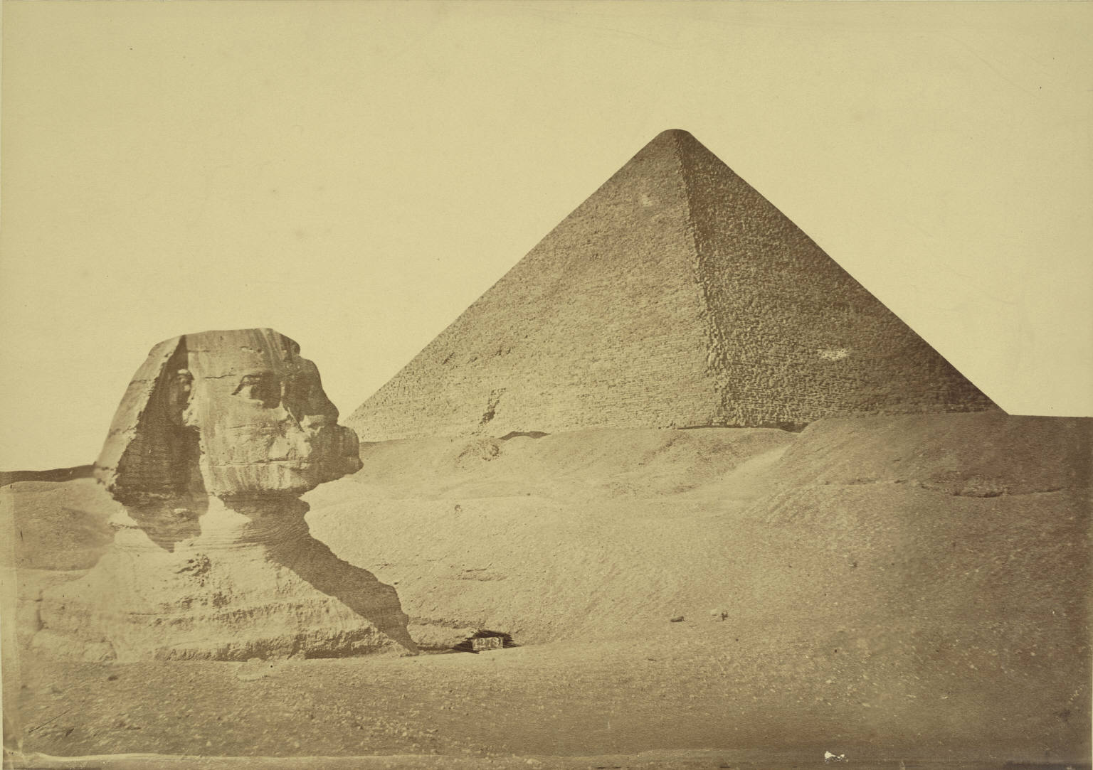
The Great Pyramid of Giza was constructed around 2570 BCE under the reign of Pharaoh Khufu on the Giza limestone plateau and is a technical masterpiece containing more than 2 million limestone and granite blocks, a total weight of 6 million ton, and originally stood 147 meters tall. This paper examines the pyramid strictly from an architectural and engineering perspective, with full respect for its sacred purpose and without any intent to diminish its spiritual significance. The placement of granite monoliths in the King’s Chamber, 43 meters above ground level, presents a logistical challenge that traditional theories, such as using only ramps, levers, or manpower, fail to adequately explain. The use of counterweight-based lifting mechanisms was already known in antiquity, for instance in Mediterranean shipyards and large temple constructions, which reinforces the plausibility of a similar approach here.
This paper proposes a hypothesis in which the Grand Gallery, the Big Void, the North Face Corridor, and an external ramp of 43 meters with a slope of 26° formed an advanced counterweight-hoisting system. The monoliths were transported via the ramp to the chevron roof of the North Face Corridor and then over the Big Void into the King’s Chamber, both movements powered by the same quartz-bearing sand counterweight in the Grand Gallery.
This model explains architectural anomalies such as the stepped ceiling, quartz-bearing sand, and chevron roofs, supported by archaeological, material, and mechanical analyses.
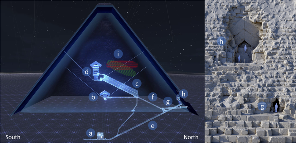
East-West cut view of the Great Pyramid and front view of the North face Chevron area. a Subterranean chamber, b queen’s chamber, c grand gallery, d king’s chamber, e descending corridor, f ascending corridor, g al-Ma’mun corridor, h north face Chevron area. Image fromProcureur et al, Nature (CCBY-SA 4.0)
2 Geo-Technical Positioning and Excavation Techniques
Prior to construction, the builders meticulously studied the subsurface of the plateau. They identified a natural fault line, visible at the location now known as the Grotto, with vertical fissures that facilitated water infiltration (Edwards, 1993; Lehner, 1997). Such geological features were also utilized in earlier pyramids, such as those of Djoser and Meidum, for subterranean passages and chambers. The deliberate use of natural weaknesses in the ground was common in antiquity, from Egyptian quarries to Mesopotamian foundations, as these features offered structural or practical advantages for excavation. Excavation was facilitated here by the locally softened limestone due to water infiltration, comparable to the construction of the Hagia Sophia in Istanbul and the Temple of Luxor, which were also, partly built on softer layers near water sources. Using knowledge of geometry, including the application of the seked and 3-4-5 triangles (Isler, 2001), the builders calculated the probable position and depth of this fault line. The exceptional precision of the pyramid’s base, deviating only a few arc-seconds from a perfect square (Petrie, 1883), demonstrates the accuracy they mastered, including for subterranean construction.
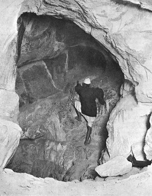
La grotte dans la pyramide de Khéops. Photo by John & Edgar Morton (PD)
From the planned location of the Northern Entrance, the builders began excavating the Descending Corridor, maintaining a consistent incline of 26° aimed at the calculated location of the fault line. This passage was carved perfectly straight over a length of approximately 105 meters, until it transitioned into the Horizontal Passage (Petrie, 1883; Lehner, 1997). For alignment, they employed an A-frame and ropes, consistent with other known Egyptian surveying instruments like the merkhet and groma-type devices, underlining their advanced technical skills. At one point, they created a niche in the western wall, believing they had reached the fault line (Hawass, 1997). However, the fault line was located further along, prompting them to extend the corridor until a second attempt was made.
During the second excavation, the fault line was successfully reached, including the natural cavity later known as the Well in the Subterranean Chamber (Lehner, 1997). This Well was the cavity the builders sought. However, they assumed the fault line extended further or that additional cavities might exist, leading them to continue digging toward what is now the Dead End Tunnel. Ultimately, the fault line proved to terminate (Edwards, 1993), rendering the tunnel purposeless.
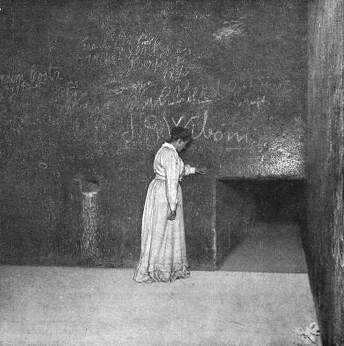
Chambre souterraine de la pyramide de Khéops. Photo by John & Edgar Morton (PD)
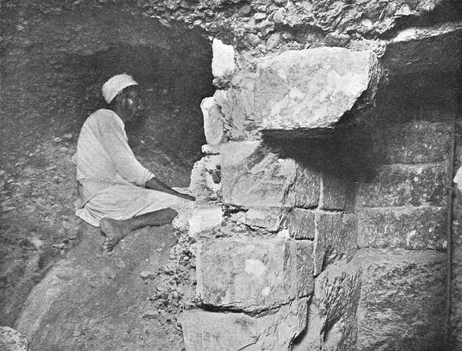
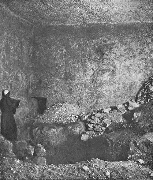
The Subterranean Chamber itself is irregular in shape and roughly finished, in stark contrast to the polished chambers above. Its form and finish suggest it was created by expanding an existing cavity, the Well, during exploratory excavation. Additionally, the Well Shaft was excavated, likely from bottom to top, to later connect the Subterranean Chamber with the Grand Gallery. This shaft, with a cross-section of approximately 60 × 70 cm, was supported during construction with diagonal wooden planks, a technique akin to ancient mining methods (Edwards, 1993). The lower portion is more roughly finished than the upper, indicating that the lower section primarily served a technical purpose.
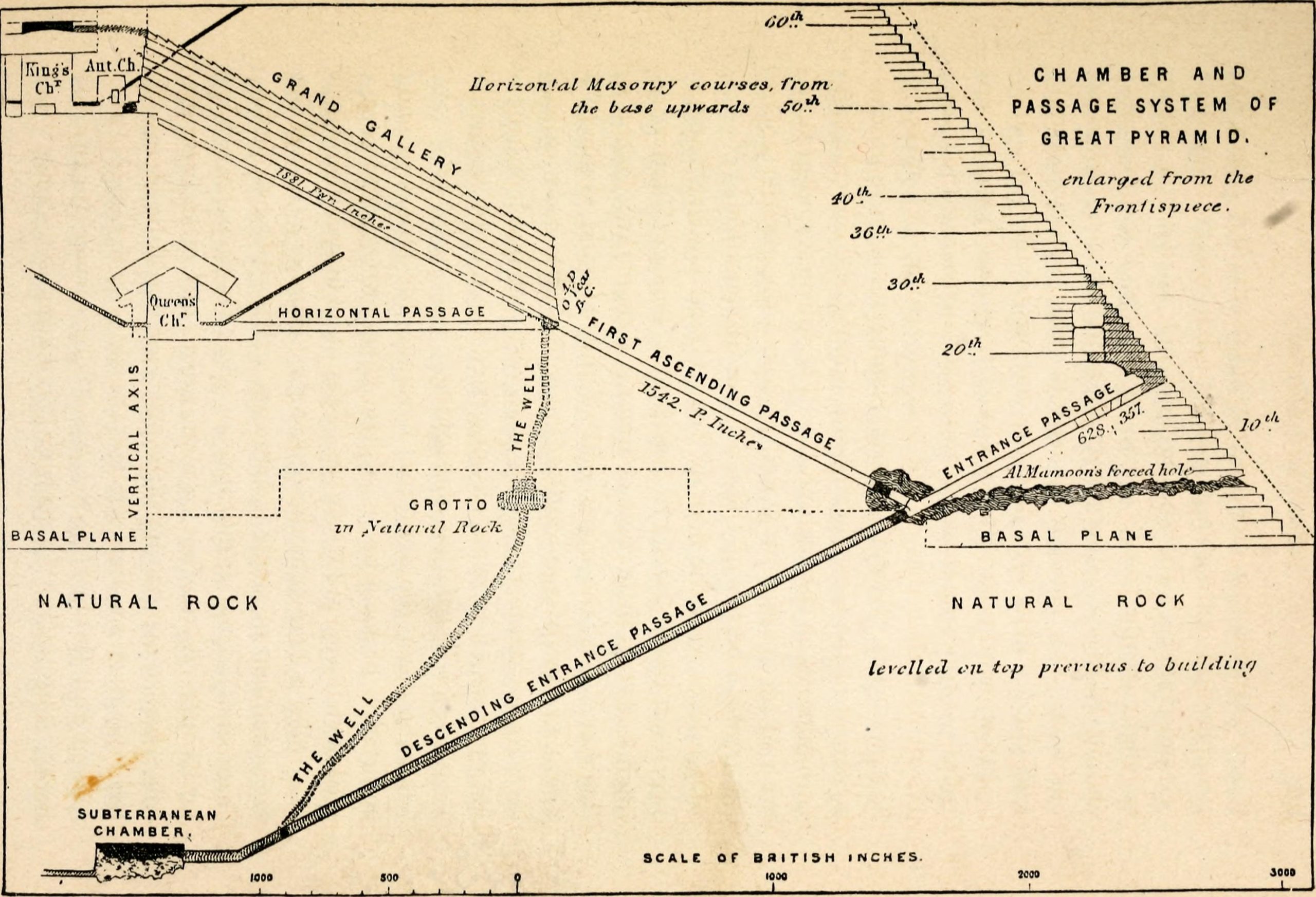
Image by Charles Taze Russell, 1891 (Public Domain)
_(14598263299).jpg)
The Subterranean Chamber exhibits traces of limescale and erosion patterns due to prolonged water infiltration through the fault line (Hassan, 1935; Petrie, 1883). Before the construction of the Aswan Dam, the groundwater level in Giza was periodically so high that Dr. Robert Bianchi could swim in these cavities as a child (pers. comm.). The chamber is only roughly finished up to a horizontal level, likely the waterline at the time, while the rest remained unfinished (Lehner, 1997). Beyond the potential role of water-logging, the prevailing explanation is that work here was halted, to focus resources and labor on the above-ground portion of the project. This led to the construction of the innovative design featuring the King’s Chamber, Queen’s Chamber, and Grand Gallery; a structure unparalleled in technical complexity and architectural refinement in antiquity. Regardless, the consistent incline of the Descending Passage (26°) and all above-ground passages and open spaces suggests they must be viewed as a cohesive whole.
Thus, the construction of the subterranean structures reveals a clear picture of a building process that integrated geological observation, geometric precision, and pragmatic adaptation. The Descending Passage, with its consistent incline over an extraordinary length, attests to technical craftsmanship. The rough Subterranean Chamber and the lower portion of the Well Shaft illustrate an iterative approach, correcting miscalculations. Their unfinished state suggests these spaces served an exploratory or technical function rather than a ceremonial one.
3 Vertical and Horizontal Features Explaining Internal and External Construction Methods
The outer casing of the Great Pyramid exhibits multiple horizontal construction lines, or narrow discontinuities, encircling the entire perimeter. These lines correspond closely to functional construction phases and internal structures (Lehner 1997; Verner 2001; Maragioglio & Rinaldi 1965).
- 21 m : Floor of the Queen’s Chamber, base of the Grand Gallery, roof of the North Face Corridor. A work platform was established at this level, with limestone blocks delivered via the North Face Corridor to complete the Queen’s Chamber and Horizontal Passage.
- 43 m : Top of the Grand Gallery, floor of the King’s Chamber. This phase reflects the construction and precise positioning of the Grand Gallery, intended as a counterweight location for granite monoliths to be placed later.
- 50 m : Ceiling of the King’s Chamber, base of the Big Void. Heavy granite blocks were delivered via the Big Void, functioning as an inclined work platform.
- 70 m : Top of the relieving chambers, upper end of the Big Void. Following the completion of granite relieving structures, construction above this level continued with lighter limestone blocks.
In addition to these horizontal markers, each pyramid face exhibits a central vertical indentation approximately 0.94 m deep at the base (Petrie 1883), giving the pyramid eight sides but providing significant additional stability by absorbing and redistributing lateral pressure on the outer casing. These vertical features indicate that the corners were first established as reference points, followed by the construction of the side planes and, finally, the infill of the core with larger blocks, likely stabilized before the start of each next platform with quartz-bearing sand.
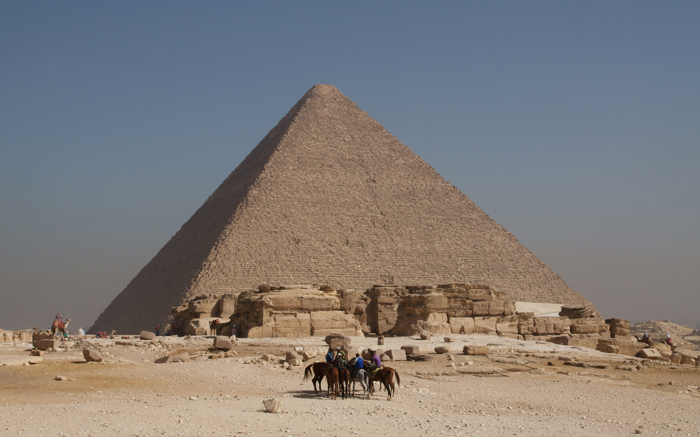
Great Pyramid of Giza. Image by kallerna, 2010 (CCBYSA3.0)
The Tura limestone casing stones, transported via the Nile (Tallet, 2017), were likely placed from top to bottom, lifted using the Herodotus machine (Herodotus, Histories, 2.125). Each layer was ground and polished after placement (Petrie, 1883). Determining whether a capstone ever existed remains beyond our capabilities.
3.1 Interpretation
The systematic alignment of horizontal lines with the North Face Corridor, the Queen’s and King’s Chambers, the Big Void, and the Grand Gallery demonstrates a phased, externally controlled construction method using stabilized work platforms. The vertical concavities confirm precise corner alignment, showing that the pyramid was built as a three-dimensional puzzle: corners first, sides second, and core last. This integrated evidence strongly supports a planned, geometrically oriented construction strategy and reduces the plausibility of internal spiral ramp hypotheses.
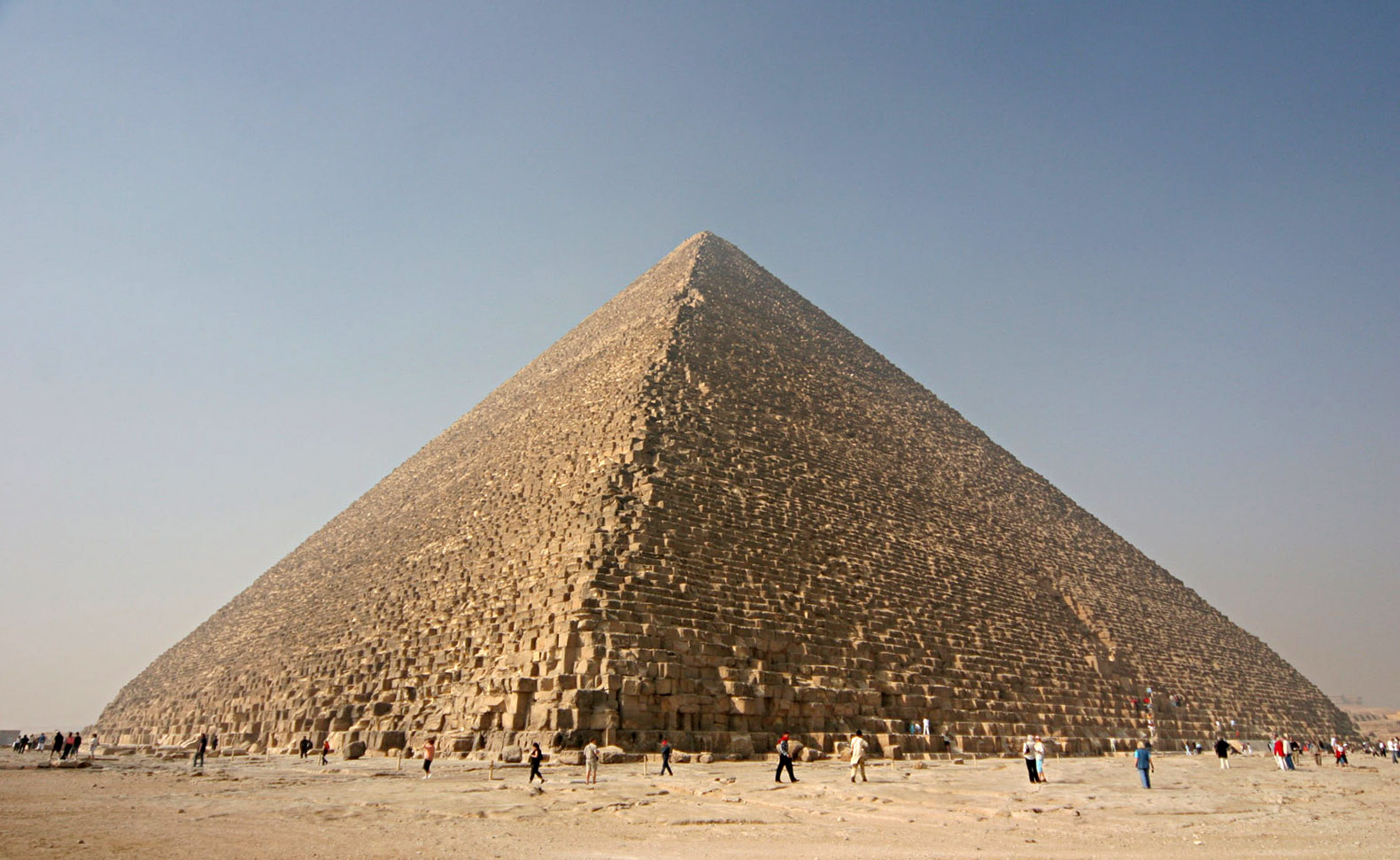
The Great Pyramid of Khufu on the Giza Plateau.Photo by Nina-no (CCBY-SA 3.0)
4 Gradual Construction of External and Internal Ramp with North Face Corridor as Intermediate Platform
For the lower layers of the Great Pyramid of Giza, built with limestone blocks from local quarries, I align with established theories that incorporate an external ramp in combination with mechanical lifting devices commonly associated with the so-called Herodotus Machine. Archaeological investigations by Lehner indicate the presence of ramp-like remains that may relate to temporary construction infrastructure built during the pyramid’s early phases. Although the precise layout, inclination, and full dimensions of this structure remain uncertain, the evidence supports the use of an external working ramp that could have provided access to the lower courses and facilitated the movement of heavy monoliths. In addition, modern interpretations suggest that temporary edge-integrated ramps could have been progressively absorbed into the growing structure by re-using debris—typically limestone chips, tafla, and gypsum—as internal packing material between core blocks, allowing the ramp to be buried as subsequent courses were laid. This approach is compatible with known logistics of Khufu’s reign, where ramps played an operational role in quarrying and transport activities, as demonstrated at Hatnub.
From this ramp level, the builders could construct the Queen’s Chamber, whose floor lies at approximately 21 m above the original plateau, and simultaneously begin the Grand Gallery. The base of the Grand Gallery also aligns with the roof level of the North Face Corridor, which is about 21 m above the plateau and features a chevron ceiling roughly 0.9 m thick, capable of withstanding dynamic forces exceeding 100 ton.
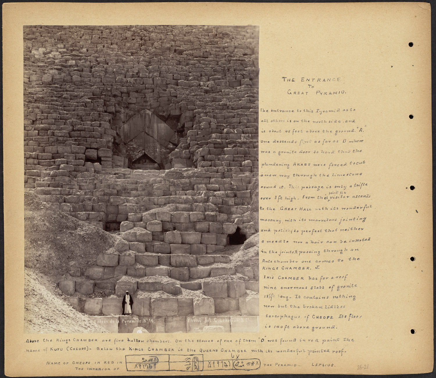
Image by William Vaughn Tupper (Public Domain)
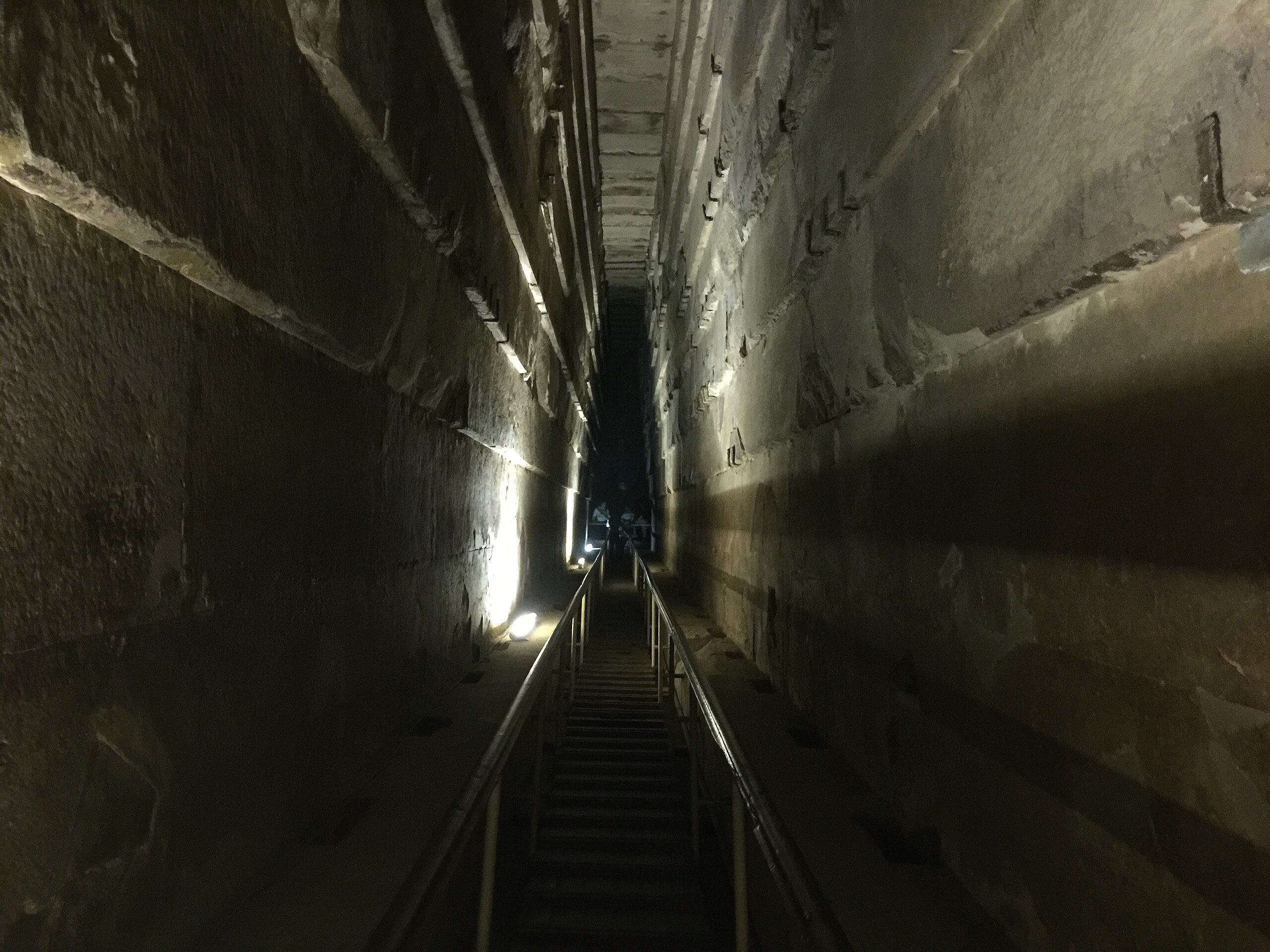
The Grand Gallery itself measures 46.7 m in length, 2.06 m in width, and 8.6 m in height, and was sealed with a stepped ceiling of seven overlapping stone layers designed to resist the enormous mechanical stresses associated with lifting and positioning granite monoliths.
Above the Grand Gallery, the Big Void, an internal space at least 30 m long, was constructed as an open working area and possible internal ramp, with subdivisions likely serving as guide channels for monoliths, as suggested by muon-tomography (Scan-Pyramids, 2017). The North Face Corridor, 9 m long with a chevron roof, lies precisely at the point where the downward projection of the Big Void would intersect and functioned as a supply and control platform.
The ramp, if extended downward from 19 m at a 26° slope to reach the surrounding plateau, would have a total length of approximately 43 m , consistent with the external ramp foundations observed outside the pyramid. This integration of internal and external ramps demonstrates a highly coordinated, phased construction strategy in which work platforms were stabilized at successive heights to facilitate the precise placement of massive stone blocks.
This evidence collectively supports a model in which the Great Pyramid was constructed using a combination of external ramps for initial elevation, internal ramps and counterweight systems for precise vertical transport, and carefully planned horizontal platforms aligned with the North Face Corridor, the Queen’s Chamber, and the Grand Gallery. The resulting structure reflects an exceptional mastery of geometry, materials, and mechanics, allowing the ancient builders to move enormous stones with precision while maintaining the architectural integrity of the pyramid.

Detail of the north side of the Cheops pyramid, located on the Giza plateau near Cairo, Egypt. Photo by Olaf Tausch (CCBY-SA 3.0)
5 The Grand Gallery as a Functional Counterweight Location
The Grand Gallery was designed as a core component of an advanced counterweight system. Its dimensions, the consistent 26° slope, which is exactly half the angle of the pyramid’s sides, and the seven-tiered ceiling exceed the requirements for human passage alone. From a mechanical perspective, this slope is appropriate for the controlled descent of heavy counterweights, such as sand-filled containers. Architecturally, the corbelled ceiling was clearly designed to accommodate the transport of mega-monoliths. Crucial in the Grand Gallery are the series of niches and 27 recesses along the side walls, regularly spaced over the entire length.
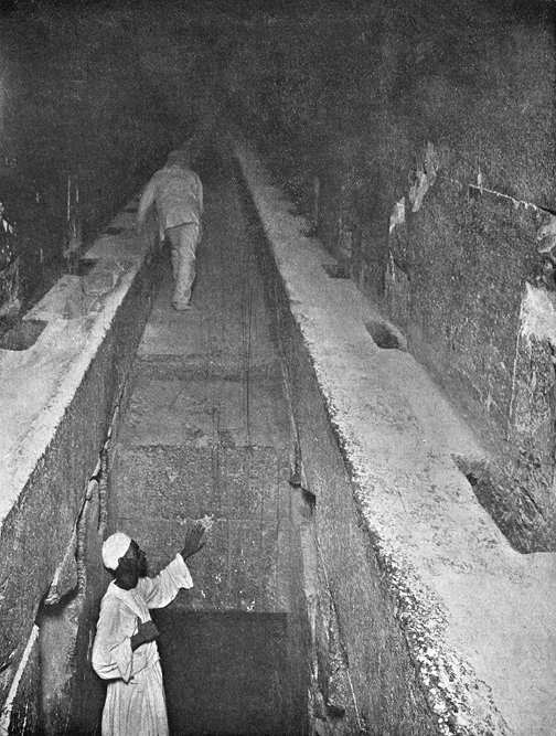
Image by John and Edgar Morton, 1910 (Public Domain)
These served as anchoring points for crossbeams, guides, or partitions that directed and stabilized the movement of the counterweight. The presence of lateral grooves supports this interpretation, as they would have allowed the placement of a wooden rail structure. The Big Step serves as the endpoint of the counterweight system, confirming its function through visible rope wear marks (Jean-Pierre Houdin). This 86 cm high limestone elevation has a triple role in the lifting mechanism: it acts as a pivot point for the ropes, a structural barrier to logically define the operating range of the stepwise moving sand containers, and most crucially, a passive emergency brake. By catching the counterweight if it suddenly lightens (due to failure), the Step prevents the subsequent freefall and crash of the heavy monolithic load.
The Grand Gallery functioned as the central component of the counterweight hoisting system, working in direct mechanical coordination with the external ramp and the Big Void (internal ramp). The external ramp supplied the granite monoliths to the North Face Corridor platform, from where they were transferred over the Big Void to the King’s Chamber, all powered by the controlled descent of the sand-filled counterweights in the Grand Gallery. Within this system, the downward motion of the ballast weight provided the energy needed to hoist granite blocks above the King’s Chamber. This same counterweight could then be reused to lower the monoliths or at least to balance for their precise placement around the King’s Chamber.
The counterweight operated according to a step wise system. The Grand Gallery housed 27 compartments, 26 of which were filled with sand containers over weighing > 3 ton each, providing a total counterweight of 78-80 ton. (The exact weight or even more, of the heaviest monolith, the weight difference between the heaviest monolith and the counterweight, including losses due to friction, could be managed manually.) One compartment was deliberately left empty to allow the containers to be removed upward one by one. Each time the 26 filled compartments ascended one level through the empty space, the granite block was pulled upward one compartment at a time to maintain stability.
The containers rested on a wooden rail that ran along both sides of the gallery at a height of 1.02 m above the floor. The narrow vertical niches in the side walls, 27 on each side, functioned as slots for wooden shutters that fixed or released the containers compartment by compartment. The wear grooves at a height of 4.22 m , just below the third corbel layer, indicates prolonged contact with the containers during their vertical movement. The space beneath this rail was reserved for the unobstructed passage of the lifting ropes, which ran underneath the containers.
The sand containers measured 0.80 m in length (distance between each vertical shutter niches), 3.20 m in height (between rail and wear zone), and a maximum of 0.50 m in width (limited by the narrowing below the third corbel layer). These dimensions yielded a volume of 1.28 m³ per container, sufficient for > 3 ton of quartz-rich sand.
A view of the Great Pyramid of Giza Grand Gallery November 2015. Photo by Keith Adler (CCBY-SA 4.0)
The space above the containers remained clear for handling and access, underlining the simplicity, efficiency, and structural integration of the system; characteristic of Egyptian construction methods.
5.1 Optimization of a Multi-Rope System for the Grand Gallery’s Hoisting Mechanism
The counterweight system in the Grand Gallery relied on precise force management through ropes and wooden rails. Lifting an 78 ton monolith with a counterweight of up to 80 ton meant the system was almost entirely self-balanced. The 2 ton weight differential provided a small, consistent net pulling force sufficient to sustain movement once initiated. A small initial manual boost of approximately 2 ton was likely required to overcome the static friction and initiate the controlled ascent. The multi-rope hoisting system was not designed to ‘bear’ a large residual load, but rather to manage, stabilize, and brake the movement.
One palm fiber rope with a tensile strength of ˜ 20 MPa was insufficient for a single Ø 17 cm rope, which would just meet the requirement with a 0% safety margin.
Using multiple ropes increased safety and reliability significantly. Two Ø 16 cm ropes could handle a combined load of approximately 82 ton, giving a 5% safety margin. Three Ø 15 cm ropes increased the total capacity to roughly 108 ton, corresponding to a 38% safety margin. Four Ø 14 cm ropes could lift about 126 ton, providing a 62% safety margin. Five Ø 13 cm ropes reached approximately 135 ton, or 73% above the required load, while six Ø 12 cm ropes gave the highest redundancy, supporting around 138 ton, a 77% safety margin.
Even with four Ø 14 cm ropes, the system was highly redundant: if one rope snapped, the remaining three could still support roughly 94 ton, significantly exceeding the total load of 78 ton. If two ropes failed simultaneously, the surviving two ropes could still carry approximately 63 ton, which, while less than the total weight, provided substantial braking capacity and would prevent catastrophic free-fall. Configurations with five or six ropes further increased redundancy: failure of two ropes still left 81–92 ton of capacity.
Friction of palm fiber ropes on wooden or stone pulleys (µ ˜ 0.2–0.3; Lucas & Harris, 1962) was minimized using vegetable oil lubrication, as observed at Lisht. The wooden rails, supported by the 27 niches, distributed forces evenly, and wear marks on the Big Step (Houdin, 2010) confirm repeated rope use under heavy loads.
This analysis shows that a multi-rope counterweight system was not only feasible but extremely reliable, capable of sustaining the lift even in the event of catastrophic failure of one or two ropes.
5.2 Comparative Analysis of Counterweight Systems in Antiquity
The proposed counterweight system in the Grand Gallery, utilizing quartz-bearing sand and a multi-rope mechanism, aligns with known engineering practices in ancient civilizations, reinforcing its technical feasibility within the capabilities of the Fourth Dynasty. Archaeological evidence from contemporaneous and later cultures demonstrates that counterweight and hoisting technologies were employed in monumental constructions, providing a broader context for the system described in this paper.
In Mesopotamia, third-millennium BCE cuneiform records describe the use of rope-and-pulley systems for lifting heavy stones during ziggurat construction (Moorey, 1994). While less complex than the proposed Grand Gallery mechanism, these systems indicate familiarity with counterweights to manage loads, suggesting that the concept was not unique to Egypt. Excavations at Byblos in the Levant, dating to the Early Bronze Age, have uncovered traces of wooden rails and rope wear marks on stone surfaces, implying the use of guided hoisting systems for temple construction (Dunand, 1950). These findings parallel the niches and grooves in the Grand Gallery, which likely served as anchoring points for wooden rails or crossbeams.
Closer to Giza, the Hatnub alabaster quarries, active during the Fourth Dynasty, provide direct evidence of related technologies. Excavations revealed a ramp system with a 20°–25° incline, supported by wooden posts and likely rails, used to transport multi-ton blocks (Tallet, 2017). The presence of wear marks on stone surfaces at Hatnub suggests repeated rope use under heavy loads, analogous to the rope wear observed on the Big Step in the Grand Gallery (Houdin, 2010). These parallels indicate that the Egyptians had the technical expertise to design a counterweight system integrated into the pyramid’s internal structure.
Inside the main quarry (Quarry P) at Hatnub. The quarry was originally roofed by rock, but the roof collapsed in antiquity. Photo by Hannah Pethen (CCBY-SA 2.0)
5.3 Mechanical Efficiency of the Counterweight System
The counterweight system in the Grand Gallery, designed to hoist 50–78 ton granite monoliths, demonstrates remarkable mechanical efficiency when analyzed through modern engineering principles. The system’s multi-rope configuration, utilizing palm fiber ropes (tensile strength 20 MPa), minimized energy losses while distributing forces effectively. With a friction coefficient of µ ˜ 0.2–0.3 for ropes on lubricated wooden or stone pulleys (Lucas & Harris, 1962), the energy loss due to friction was approximately 10–15% per hoisting cycle, based on calculations for a 150 meter rope path. For an 78 ton monolith and a counterweight of 80 ton, the 2 ton weight differential provided the necessary net force to overcome kinetic friction. An initial manual boost of approximately 2 ton was likely required to overcome static friction and initiate movement, achievable by a small team of workers by hand or simply to add or release sand.
The use of multiple ropes (e.g., four Ø 14 cm ropes, total capacity ~ 126 ton) ensured a safety margin of ~ 62%, reducing the risk of rope failure and optimizing force distribution across the system. The Grand Gallery’s 26° incline further enhanced efficiency by aligning the counterweight’s gravitational potential energy with the monolith’s vertical lift, minimizing lateral forces. Modern simulations of similar systems suggest an overall mechanical efficiency of ~ 80–85%, comparable to early industrial hoists (Beltagy, 2022). The niches and grooves, likely anchoring wooden rails, maintained alignment, reducing oscillatory losses. This analysis, grounded in measurable parameters, confirms that the system was not only feasible but optimized for energy efficiency within the technological constraints of the Fourth Dynasty.
5.4 The 26° Incline
Why 26 degrees is the sweet spot and the key. At approximately 26 degrees, the friction between granite, limestone, and a thin layer of quartz sand is precisely strong enough that a heavy block (or the counterweight) remains completely stable—it does not slide on its own. Yet it is on the edge: with the smallest push or a very slight increase in weight, it begins to move. At the moment of perfect equilibrium between the block and the counterweight (both precisely at 26 degrees), the block could theoretically be nudged upward with a single hand. In practice, of course, multiple workers and adjustments with sand were used, but this demonstrates how extremely low the required force was. The incline carried the bulk of the weight, friction kept everything in perfect balance until movement was desired, and the ropes were barely under tension—certainly no more than necessary, preventing overloading of simple wooden pulleys.
The counterweight was sectional. The Grand Gallery was where the counterweight operated: a system of adjustable, sectional containers filled with sand. A solid, fixed counterweight (for example, one enormous block of 60–80 tons) would never have had enough space to descend fully during a complete lifting cycle. The Gallery is long (approximately 47 meters), narrow, and inclined—a large fixed weight would get stuck or fail to gain sufficient height to lift a megamonolith of tens of tons. By making it sectional (several smaller containers that could be filled or emptied individually), the counterweight could be precisely adjusted and lowered step by step. This gave the builders fine control: add a few extra buckets of sand to start, remove sand to slow or stop.
The megamonolith on the mirrored slope; the Big Void. The heavy block itself (the megamonolith, such as the enormous granite ceiling beams of the King’s Chamber) rested on a mirrored slope—an incline of exactly the same 26 degrees, but in the opposite direction. This mirrored slope runs parallel to the Grand Gallery and aligns with the axis of the Big Void (the large, hidden empty space above, discovered via muon scans). A rope connected the block to the sectional counterweight in the Gallery over a simple pulley (likely a rough wooden beam or log).
How it worked in practice:
- Start: add a few buckets of sand to the counterweight ? the system slowly begins to move (block rises, counterweight descends).
- Stop: remove sand ? everything stabilizes naturally.
Safe and repeatable: no enormous pulling forces, no risk of uncontrollable falls.
From this follows a logical and elegant conclusion for the entire pyramid: the 26-degree incline was the slope chosen by the builders as the most “mobile” angle—the sweet spot where friction and gravity balance perfectly so that a block or counterweight remains stable but moves immediately and controllably with minimal extra impulse (a little sand or a slight push). This angle maximizes transportability and repeatability with extremely low forces on ropes and pulleys.
For the exterior of the pyramid, the exact opposite requirement applied: maximum stability. Nothing could slide on its own; the structure had to remain unshakable for centuries under its own weight, wind, earthquakes, and temperature variations. The most stable slope is therefore the angle where the component of the weight acting parallel to the incline is much smaller than at 26 degrees, in other words, a significantly steeper slope. The most natural and geometrically coherent choice is then to make the stable exterior slope approximately twice as steep as the mobile internal slope: 2 × 26° = 52°.
This creates a direct, physics-driven relationship between the two angles:
- 26° = optimal mobility and energy efficiency for the internal lifting system
- 52° = optimal stability and structural integrity for the exterior
This is no coincidence but a deliberate design decision based on lessons from previous pyramids:
- The Bent Pyramid originally began with too steep an exterior slope of approximately 54° ? this caused collapse problems (cracks, subsidence), forcing them to flatten to about 43° mid-construction to prevent further catastrophe.
- The Red Pyramid deliberately chose a gentle exterior slope of about 43° ? this avoided structural failure but made the build slower and less efficient in height gain per added stone volume.
Thus, the pyramid combines in a single geometry two perfectly coordinated properties: extremely efficient lifting inside and rock-solid durability outside. The entire shape of the Great Pyramid is a logical outcome of a single key parameter: 26 degrees as the most mobile angle.
In short, 26 degrees is the sweet spot that dictates everything. It combines simplicity (straight incline, sectional sand containers, simple ropes over logs) with force management (ropes barely loaded, movement with minimal effort; theoretically even achievable with one hand at the critical moment). The Grand Gallery was not a ceremonial space; it was the pyramid’s built-in lifting machine, perfectly tuned to how stone + sand behave. That explains why this angle recurs everywhere: it had to work; and it worked brilliantly.
Alternatively, a limited quantity of water (approximately 1000 kg) could have been added to the top container just before descent. This extra weight would overcome static friction and initiate movement down the 26° slope of the Grand Gallery. Once in motion, the water would drain automatically through the container towards the Well Shaft, gradually reducing the pulling force and allowing the system to come to a smooth stop.
6 Supply of Quartz-Bearing Sand as Counterweight
Quartz-bearing sand (Scan Pyramids, 2017), likely sourced from Gebel Ahmar (100 km from Giza) or El Tor (400 km away), was transported via the external ramp to the Grand Gallery. With a density of 2.5 g/cm³ (higher than the local desert sand at 2.1 g/cm³), this sand was ideal as counterweight. A volume of 32 m³ provided 80 ton (32 m³ × 2 500 kg/m³ = 80 000 kg) and only 78 ton needed, used as counterweight in the hoisting system. But this sand was valuable not only as ballast; its more rounded shape and hardness also provided up to 50% better fluidity, both as a transport base and by itself. This becomes clearer later, as the pyramid is filled with this quartz-bearing sand in nearly every cavity.
6.1 Properties of Quartz-Bearing Sand
The use of quartz-bearing sand from Gebel Ahmar or El Tor (density 2.5 g/cm³) was critical for the counterweight system and stabilization. Its grain size (ca. 0.5–1 mm) and rounded shape provided up to 50% higher fluidity than local desert sand (2.1 g/cm³), enhancing efficiency as a counterweight and transport base (Brier & Houdin, 2008). Modern tests with comparable quartz sand in concrete mixtures show its hardness (Mohs scale 7) and low friction coefficient (0.02 on polished stone) were ideal for sliding monoliths. The presence of this sand in nearly every cavity of the pyramid (Scan-Pyramids, 2024) confirms its multifunctional application.
7 Installation of the Counterweight Hoisting System and Transport of Monoliths to the North Face Corridor Platform
The counterweight hoisting system was loaded, with the Big Void as an open workspace and the 80 ton quartz sand counterweight in the Grand Gallery. Ropes made of papyrus or palm fiber (tensile strength: 20 MPa) with a bundle diameter of 15 cm, supported by wooden or stone pulleys (findings at Lahun), could withstand 78 ton loads. This system transported the granite monoliths (50–78 ton) over the external ramp to the chevron roof of the North Face Corridor, which served as a supply and operating platform and the place where the ropes were realigned. The double chevron roof withstood forces over 100 ton. From this 9-meter-long horizontal platform, the monoliths were transferred to the hoisting system in the Big Void. The 26° slope in the Big Void minimized friction on lubricated limestone or wet wooden floors (friction coefficient: 0.02, as at Lisht). Or on the quartz sand, acting like mini marbles. The so-called “fake” Northern Entrance, known as the North Face Corridor, was not a pointless decoration but served as a transfer point for the hoisting system that brought the heavy monoliths to the Big Void. At the same time, this corridor functioned as an effective diversion: it appears as the main entrance, while the real access is hidden just below it. By emphasizing the visibility and importance of the North Face Corridor, attention would automatically be drawn to it upon discovery, causing clues at the real entrance, just underneath, to be overlooked or even buried. This dual strategy aligns with earlier construction experiments under Pharaoh Sneferu (Khufu’s father), where multiple entrances and complex structures were used to technically and visually protect the pyramids. In the Great Pyramid, this principle was perfected: a functional platform that also served as camouflage for the real and better-hidden entrance just below it.
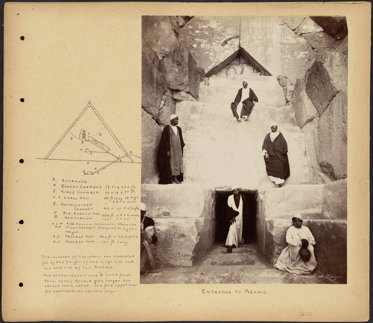
Image by William Vaughn Tupper (Public Domain)
7.1 Archaeological Evidence of Pulleys
Archaeological evidence indicates that the hoisting system used pulleys made of hardwood or polished stone. Some examples from comparable sites, such as Lahun (Arnold, 1991), suggest diameters around 50 cm, large enough to handle heavy loads, with axles capable of withstanding forces up to 100 ton, sufficient for the 78 ton monoliths. Slippage and wear marks (Houdin, 2010) on the treads indicate repeated rope contact, showing that pulleys distributed forces and guided ropes along intended paths. The exact number and positions of the pulleys inside the pyramid are not preserved; conclusions about these aspects are based on indirect evidence and analogies.
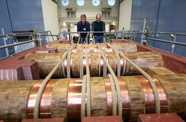
Image by Frank Mueller-Roemer, 2024 (CCBYSA4.0)
7.2 Technical Analysis of Rope Configurations
The counterweight system in the Grand Gallery relied on robust palm fiber ropes, whose construction and load-bearing capacity were critical to hoisting 50–78-ton granite monoliths. Recent analyses of Old Kingdom rope technology (Ryan & Hansen, 2023) reveal advanced braiding techniques that enhanced tensile strength and durability. Palm fiber ropes, typically 12–14 cm in diameter, were crafted using a three-strand braiding method, achieving a tensile strength of 20 MPa. For an 78 ton monolith, a configuration of four ropes, each with a breaking strength of ~308 kN, provided a total capacity of ~1232 kN, yielding a safety factor of ~174%. This minimized the risk of failure under dynamic loads.
The ropes were likely lubricated with animal fat to reduce friction (µ ˜ 0.2 on polished stone pulleys), as evidenced by chemical residues on Lahun ropes (Arnold, 1991). The Grand Gallery’s 27 niches, spaced at 80 cm intervals, anchored wooden crossbeams that guided these ropes, ensuring even load distribution and preventing tangling. Calculations indicate that a 150 meter rope path, traversing the Big Void and North Face Corridor, required ~3–4 kN of additional force to overcome friction, achievable by a team of 10–15 workers. Comparative evidence from the Hatnub quarries, where braided ropes supported 10 ton loads, confirms the feasibility of this configuration (Tallet, 2017). The multi-rope system’s redundancy and precision underscore the Fourth Dynasty’s engineering sophistication, enabling efficient and safe hoisting operations.
8 Transport of Monoliths via the Big Void to the King’s Chamber
The Big Void, a space at least 30 meters long above the Grand Gallery with his upper section above the King’s Chamber, was possibly used to hoist the heavy granite blocks upward. A counterweight in the Grand Gallery lifted the blocks, while internal subdivisions or guide channels within the Big Void may have directed their movement (Scan-Pyramids, 2017). An unconfirmed small cavity of about 0.5 m³ above the Big Void could have served as an anchor point for ropes or pulleys, explaining the precision of the hoisting system (Cairo Symposium, 2024).
A full hoisting cycle for a single monolith—moving at 1 cm/s over 150 meters, including reattaching ropes and reloading—took approximately 8 hours, allowing one block to be positioned each day. Recent muon tomography confirms the length of the Big Void and suggests the presence of internal guiding structures (Scan-Pyramids, 2024), although further scans are needed to verify all details.

The King’s Chamber, Great Pyramid of Khufu. Image by Egypt Archive (CC0)
9 Sand Filling, Pressure Distribution, and Drainage in the Great Pyramid
During the construction of the Great Pyramid, quartz-bearing sand (density 2.5 g/cm³, probably from Gebel Ahmar) was used multifunctionally as temporary support, counterweight, and drainage/filling material. This sand provided stability and precision in placing heavy roof monoliths in the Grand Gallery, Queen’s Chamber, and King’s Chamber, followed by possible controlled drainage to the Subterranean Chamber by gravity.
9.1 Support of the Corbelled Roof in the Grand Gallery
In the first construction phase, sand was transported via the external ramp (26°) into the Grand Gallery (46.7 m long, 2.06 m wide, 8.6 m high) to support the cor-belled roof of seven overlapping stone layers. Stabilized with temporary form-work, the sand evenly distributed pressure during the placement of the heavy limestone layers, which had to withstand forces > 100 ton. This use of sand as temporary support aligns with Egyptian construction techniques, such as in mastabas.
9.2 Transfer to the Queen’s Chamber and King’s Chamber
After completing the cor-belled roof, part of the sand was carefully moved to the Queen’s Chamber (approx. 21 m height) and King’s Chamber (approx. 43 m height) via the known accesses, with lower sand to the Queen’s Chamber and upper sand to the King’s Chamber or simply through the still open roof, up to above roof level. In both chambers, the sand played a supporting role in placing the roof monoliths (limestone in the Queen’s Chamber, granite in the King’s Chamber). Narrow shafts (the ventilation shafts approx. 20 cm wide) in the chambers acted as pressure valves, regulating the sand pressure to prevent cracking or subsidence. Plugs sealed the entrances to prevent premature leakage, with damage to the limestone entrance of the Queen’s Chamber upon removal, unlike the granite entrance of the King’s Chamber.
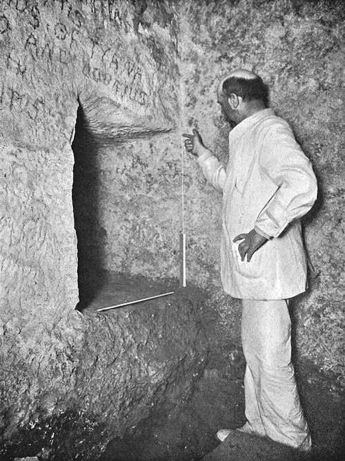
Photo John and Edgar Morton, 1910 (Public Domain)
hoto John and Edgar Morton, 1910 (Public Domain)
9.3 Sand as Counterweight in the Grand Gallery
The remaining sand in the Grand Gallery was reused as the 80 ton counterweight for the hoisting system. Guided by niches, grooves, and the Big Step, the sand was moved in stable containers along the 26° incline, powered by papyrus or palm fiber ropes (tensile strength 20 MPa).
9.4 Drainage to the Subterranean Chamber
After completing the roof constructions and hoisting process, all sand was carefully drained via the Well Shaft to the Subterranean Chamber (volume +/- 450 m³). This unfinished space served as the final reservoir, with the sand volumes from the King’s Chamber; max 275 m³, Queen’s Chamber max 135 m³, and Grand Gallery max 35 m³, still fitting exactly (+/- 450 m³). The natural slope to the corridors, especially the Well Shaft, and the rough finishing of the subterranean chamber support this function. The presence of other debris, during construction, was also naturally deposited there by gravity.
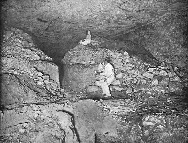
Image by John and Edgar Morton, 1910(Public Domain)
9.5 Sand Summary
The sand played a crucial role both as support and later as counterweight, regulated by shafts and plugs. This rational system explains architectural anomalies such as the pressure shafts, damage to the Queen’s Chamber entrance, the unfinished subterranean chamber, and certainly the ubiquitous presence of this sand, in each cavity, testifies to Egyptian engineering skill in overcoming structural and logistical challenges without speculative explanations.
9.6 Comparative Analysis with Other Pyramids
The application of a counterweight system finds parallels in other Egyptian constructions. At the Hatnub quarry, remains of a ramp with a similar slope (ca. 20°–25°) were found, including traces of wooden rails (Tallet, 2017). The Djoser pyramid shows evidence of temporary sand filling for roof stability, similar to the proposed use in the Grand Gallery and chambers (Verner, 2001). These precedents strengthen the plausibility of the proposed system and place it within the known technological capabilities of the Old Kingdom. The hermetic sealing of the pyramid, with granite plugs and sand drainage to the Subterranean Chamber, may reflect a symbolic purpose: creating an eternal sanctuary for Khufu’s ka. The precision of the King’s Chamber and its inaccessibility suggest a ritual function, where technical complexity expressed spiritual perfection, as seen in earlier pyramids of Sneferu (Verner, 2001).
10 Assembly of the King’s Chamber
From the upper opening of the Big Void, the monoliths were lowered to the King’s Chamber: first the walls, then the sarcophagus, followed by the roof itself, and lastly the relieving chambers. This also clarifies the debate about whether the sarcophagus was built in or placed afterwards: logically, it had to be positioned before the roof. Notably, the three trapdoors (each one square meter), which have now been shown to have been installed from above, could only have been inserted after the walls were erected; a sequence that confirms construction logic. The counterweight, adjustable via the partitions in the Gallery, neutralized gravity for precise positioning of these elements, together with the stabilizing sand and pressure valves in the chambers.
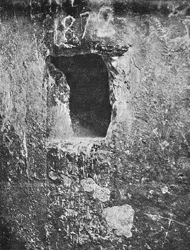
Image by John and Edgar Morton, 1910 (Public Domain)
They could simply have let the bottom container drain until the moment of perfect balance for millimeter-accurate placement.
After completion, the Big Void was left unused, and the shafts of the Queen’s Chamber were not further developed, thus ending in dead ends. Since there were very likely guiding walls or stone partitions present (Scan-Pyramids, 2017), this explains why what was once an open workspace or transport zone eventually became a “void” as construction progressed. The King’s Chamber was technically designed to facilitate this unique building phase but could, of course, later acquire ceremonial significance.
11. Closure and Sealing of the Great Pyramid of Khufu
The sealing of the Great Pyramid of Khufu was a meticulously orchestrated process, based on gravity, sand logistics, and architectural precision. Through a sequence of steps, the pyramid was hermetically sealed and symbolically rendered inaccessible.
11.1 Completion of the Queen’s Chamber and Sand Logistics
After the completion of the Queen’s Chamber, the support sand became redundant. From the future location of the Horizontal Passage, this sand was transferred to the Grand Gallery, where it was temporarily stored for reuse. The sand still served as an aid for the finishing of the Grand Gallery and possibly also for the King’s Chamber (Goyon, 1985; Lehner, 1997).
This phase demonstrates clear logistical optimization: the sand from the Queen’s Chamber was not immediately removed, but reused multiple times in subsequent construction steps.

https://commons.wikimedia.org/wiki/File:Millennial_dawn_(1891)_(14784577392).jpg
11.2 Emptying of the King’s Chamber and Removal via the Well Shaft
Following the finishing of the King’s Chamber, the supporting sand here too was guided through the Antechamber to the Grand Gallery. Ultimately, all the sand from all chambers, along with the 80 ton ballast of the hoisting system, was located there.
The systematic removal could begin: workers removed the thresholds and partition walls, after which all the sand and construction debris flowed via the Well Shaft to the Subterranean Chamber. With a capacity of approximately 450 m³, the Subterranean Chamber offered sufficient space for this material.
The presence of considerable amounts of sand and debris in the Subterranean Chamber and the passages leading to it, as described by Caviglia and Petrie (1883), supports the hypothesis that the Well Shaft functioned as a one-way channel, from top to bottom. Moreover, given the architecture, it is physically impossible for material to have accumulated in the shaft from below.
11.3 Placement of the Blocking Stone
After the emptying of the upper chambers and passages, the blocking stone was presumably placed first at the top exit of the Well Shaft, near the floor of the Grand Gallery. Direct evidence is lacking, but traces of hammering at the top of the Well Shaft, often attributed to intruders like the men of Al-Ma’mun (9th century CE), suggest that the shaft may have originally been sealed and hidden from above.
The great pyramid passages and chambers, 1910. Image by John and Edgar Morton (Public Domain)
11.4 Placement of Granite Portcullises
Next, the three granite portcullises were lowered into the vertical grooves in the Antechamber. These grooves were designed to prevent leverage, thereby permanently and hermetically sealing the King’s Chamber (Lehner, 1997).
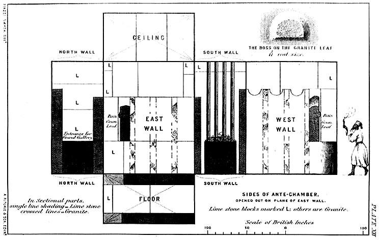
Image by Charles Piazzi Smyth, 1877 (Public Domain)
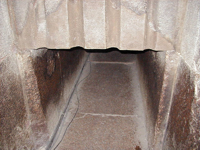
Image by Jon Bodsworth (Public Domain)
11.5 Final Sealing with Granite Plugs
With the portcullises in place, the definitive sealing of the internal passages followed. The three granite plugs, previously stored in the Grand Gallery, were lowered one by one into the Ascending Passage.
It is at this stage that the blocking stone gains its crucial necessity: because the upper exit of the Well Shaft was already closed, the plugs could slide downwards over a smooth surface and thus completely seal off the internal access. This made the Well Shaft an integral part of the hermetic locking mechanism.
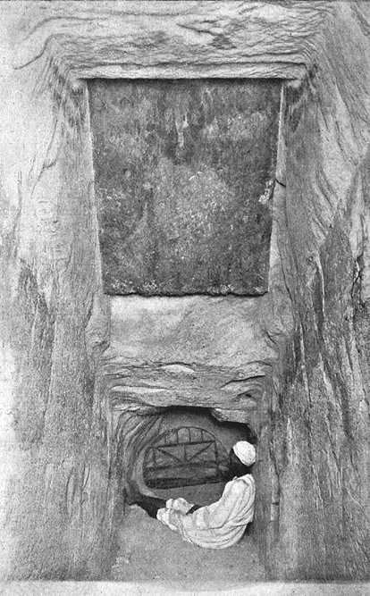
Photo John and Edgar Morton, 1910 (Public Domain)
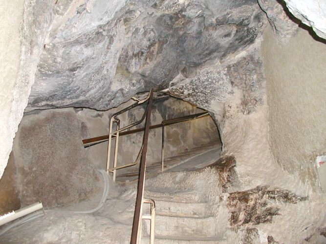
Image by Jon Bodsworth, 2007 (Public Domain)
11.6 Escape of the Workers
After the portcullises and plugs were put in place, only one possible exit remained for the workers. From the highest point of the Grand Gallery, they reached a narrow horizontal escape tunnel (Davison’s Tunnel), which led to Davison’s Chamber, the lowest Relieving Chamber above the King’s Chamber (Davison, 1765; Vyse, 1837; Edgar, 1910).
With potential use of ropes and help from outside, the workers could use this narrow passage once to exit the pyramid. However, in the subsequent building and sealing phases, this tunnel became increasingly buried within the pyramid’s construction.
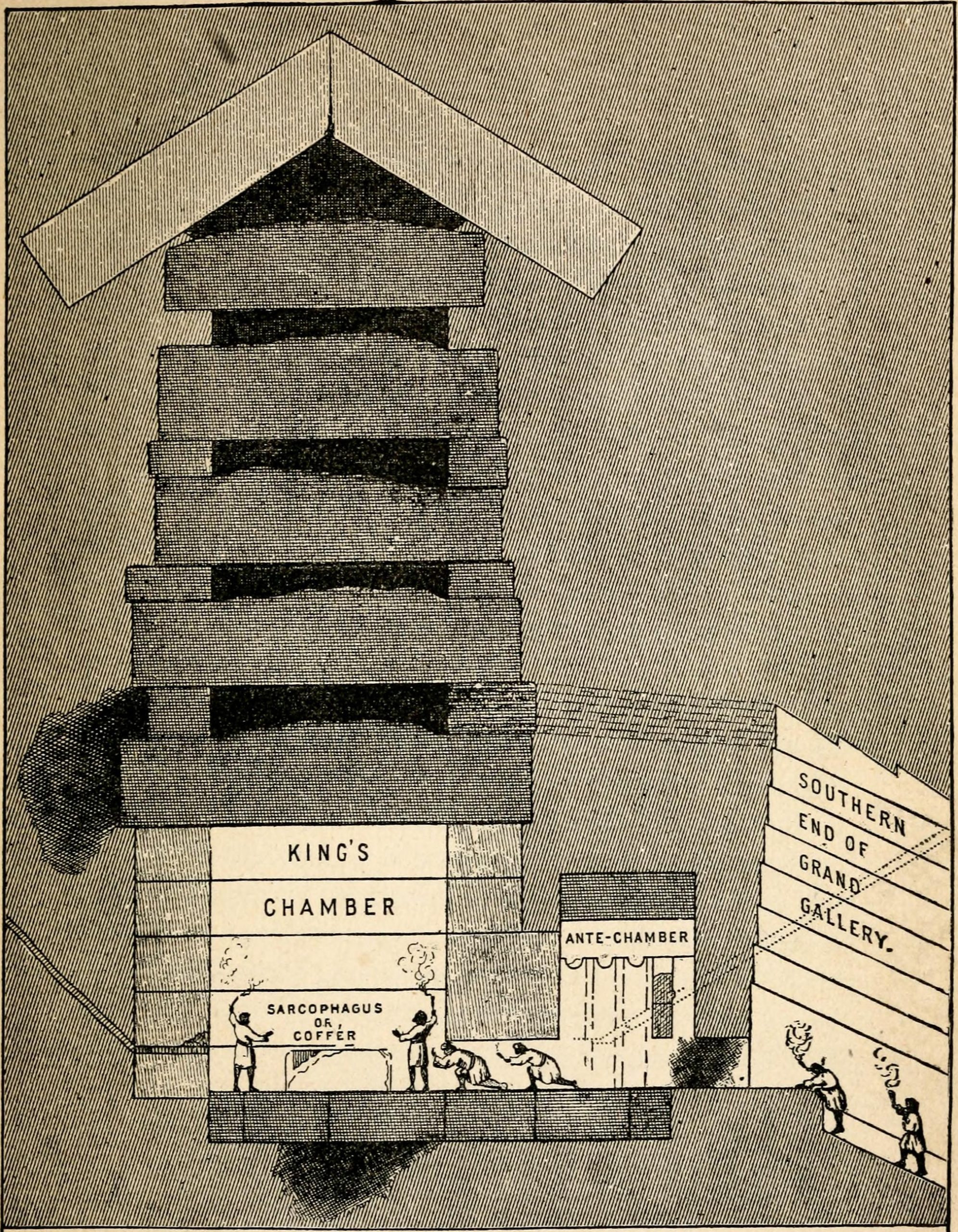
Image by Charles Taze Russell, 1891 (Public Domain)
_(14784575922).jpg)
11.7 A Hermetic Masterpiece
Through an ingenious combination of sand logistics and gravity, the Queen’s Chamber, the King’s Chamber, and the Grand Gallery were completely emptied, while the Subterranean Chamber filled up. The sealed Well Shaft, the 3 granite portcullises, the 3 granite plugs, and the narrow escape tunnel together formed an irreversible locking mechanism.
This dual physical security, as well as the symbolic irreversibility, made the Great Pyramid a hermetic masterpiece, whose inaccessibility was likely based on the combination of sand logistics, gravity, and ingenious sealing methods.
12 Comparative Analysis of Alternative Construction Hypotheses
To evaluate the completeness and robustness of the presented mechanical model of the Great Pyramid, a systematic comparison has been made with the best-known alternative theories, including those of Jean-Pierre Houdin, Mark Lehner, Simon Scheuring and Zahi Hawass.
The mechanical model offers an internally coherent system in which every element of the pyramid is functionally necessary. The Grand Gallery, Big Void, North Face Corridor, niches and corbels are not decorative or symbolic additions, but integral to the placement of the megamonoliths and the transport mechanism using sectional counterweights. This enables blocks of 50 to 78 tons to be positioned with high precision in the upper chambers, within the practical capabilities of the Old Kingdom. The use of sectional counterweights makes the system physically feasible and ensures that the counterweight remains inside the Grand Gallery, guaranteeing efficiency, safety and controllability.
The ramp and labour hypothesis as described by Lehner can plausibly explain the lower layers of the pyramid, where the masses and distances are manageable. However, for the megamonoliths and internal structures, this theory offers no explanation, where physical and logistical challenges are critical. As a result, his model only explains part of the construction and leaves the rest unexplained.
Houdin’s internal ramp theory introduces a spiral or zigzag ramp. However, no archaeological evidence has ever been found for such a construction, and it seems unlikely that an Old Kingdom architect would apply a dual-ramp system, since everything was designed to be energy- and labour-efficient. His theory remains largely hypothetical and provides a less convincing explanation for the precise placement of the megamonoliths and the functional role of internal spaces such as the Grand Gallery and the Big Void.
Scheuring proposes internal pulley-like systems and counterweights in passages such as the Grand Gallery and Antechamber. Although mechanically ingenious, his theory has several points of concern: the passages are physically problematic for the safe and repeated movement of large blocks, and the re-interpretation of the Antechamber as a pulley station is incorrect, as its function as a portcullis system with granite slabs is well established. Moreover, the model appears more complex and riskier than what is historically plausible for the Old Kingdom.
Water-based techniques are highly impractical under the extreme weights of 50 to 78 tons. There was probably no technology in the Old Kingdom capable of realising watertight constructions that could guarantee the required precision and stability.
Symbolic or ritual theories, as proposed by Hawass, offer at most interpretative explanations, but provide no functional solution for the actual construction.
The mechanical model presented in this paper stands out for its high degree of closure on physical, mathematical and functional levels. It simultaneously explains all aspects, from the lower layers to the megamonoliths, from the Grand Gallery to the Big Void and the niches, as functionally necessary and physically executable within the technology of the Old Kingdom. Other theories remain limited on at least one crucial point.This suggests that the pyramid is the result of a highly refined mechanical design in which efficiency, precision and mathematical consistency are central.
13 Logistics and Labor Organization
Construction of the Great Pyramid likely involved a highly organized workforce and a dual reliance on both waterborne and land-based logistical systems. Based on the Journal of Mere, the papyrus logbook of Inspector Merer (Tallet, 2017), an estimated 2 000–3 000 workers per shift were involved in transporting stone, moving between 200–300 ton daily. Archaeological evidence from the workers’ settlement at Heit el-Ghurab, also known as the “Lost City of the Pyramid Builders,” suggests that this village could house 6 000–7 000 workers, with an additional 12 000–14 000 personnel in supporting roles such as bakers, brewers, butchers, and water carriers (Lehner, 1997). Excavations conducted by Mark Lehner and the AERA team since 1988, approximately 400 meters south of the Sphinx, reveal an advanced infrastructure of workshops (wood, cupper and stone), hospitals, and communal dormitories that ensured the continuous supply and welfare of the workforce.
Recent paleohydrological studies provide crucial context for the logistical system that supported the movement of construction materials. The discovery of the Ahramat branch of the Nile (Ghoneim et al., 2024) has demonstrated that the Giza plateau was directly connected to an active Nile watercourse between the third and second millennia BCE. Satellite radar, field geophysics, and sediment cores confirm that this branch, ranging from 200–500 meters in width and 2–8 meters in depth (Nature Portfolio, 2024), supported seasonal inlets such as the “Giza Inlet.” These inlets functioned as harbors at the foot of the pyramid complexes, where boats could unload cargo. The inlet system is interpreted as the logistical hub for the delivery of limestone from Tura and granitic monoliths from Aswan, the latter weighing up to 50–80 ton (Lehner, 1997; Rossi, 2003). Earlier work by Sheisha et al. (2022) using pollen records confirmed that local Nile channels maintained sufficient water levels during the Fourth Dynasty to facilitate boat access to these harbors.
Functionally, two harbor systems must be distinguished. The Giza Inlet, connected to the Ahramat branch, enabled the direct delivery of large shipments, including the granite beams for the King’s Chamber, from long-distance transport routes. In contrast, local valley temples functioned as reception and redistribution points where stones arriving from nearby quarries, such as Tura limestone, were unloaded and staged for land transport.
Coordination of these methods required specialized labor divisions: teams for filling and emptying sand counterweights, teams for rope handling, and teams for final positioning of blocks. Calculations suggest workdays in two shifts, with two times eight-hour effective hoisting cycles. This integration of harbor-based supply lines and highly regimented labor at Heit el-Ghurab explains how such a monumental construction could be completed within approximately 20 years.
13.1 Strategic Location Choice
The workers’ village of Heit el-Ghurab was located directly next to the harbor of Khafre’s Valley Temple, highlighting the close interconnection between settlement and logistical infrastructure. The choice of the Giza Plateau was largely pragmatic and logistical. The plateau offered three crucial conditions: (1) a solid limestone foundation with sufficient space for monumental construction, (2) direct access to the Nile via the Giza Inlet and the valley temple harbors, and (3) space for a large workers settlement adjacent to the supply points. This combination of building ground, harbor, and village explains why Giza became the focal center of pyramid construction during the Fourth Dynasty.
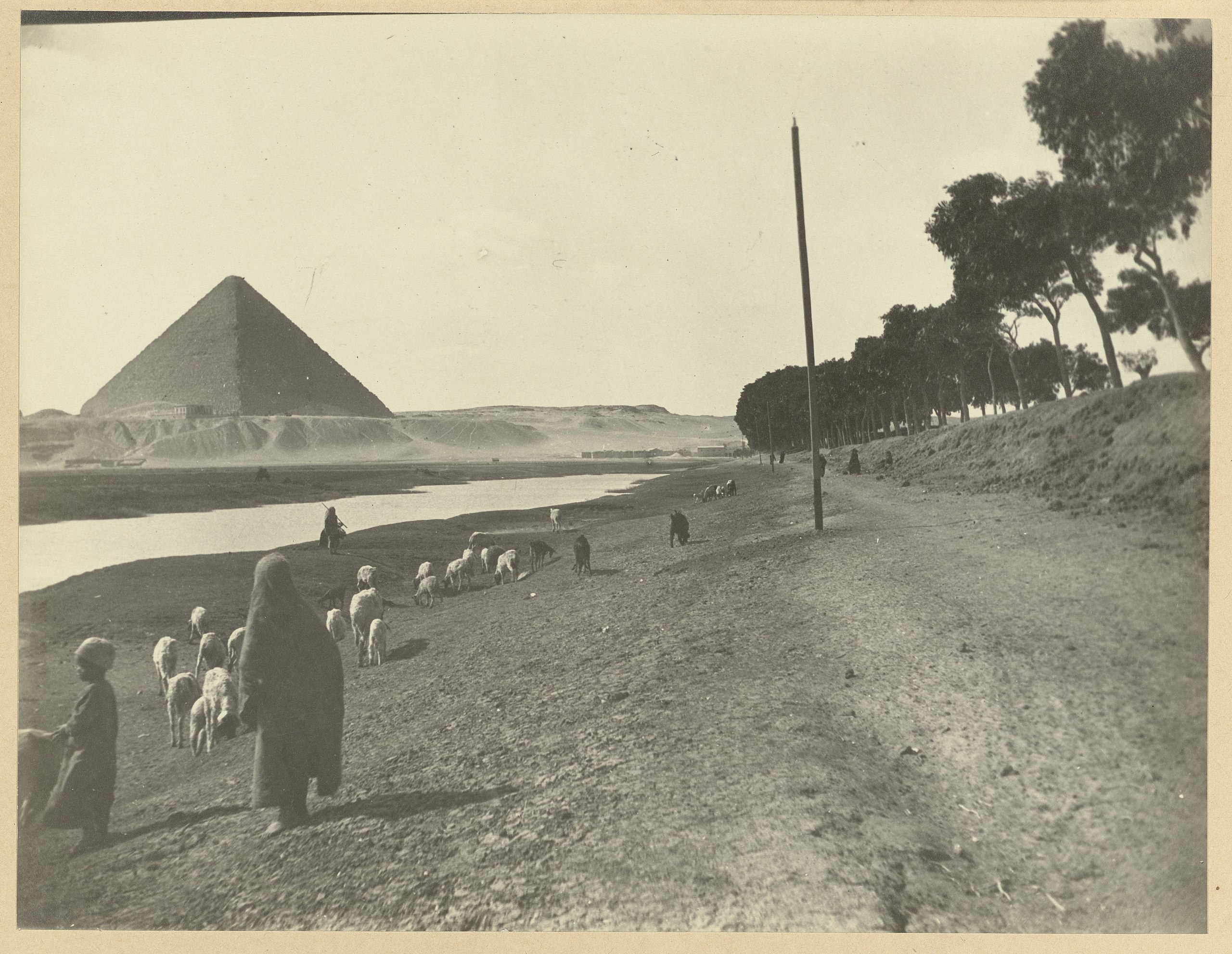
Image by Rijksmuseum, 1895-1915 (CC0)
14 Experimental Validation
A scale experiment, similar to Stonehenge reconstructions (Richards, 2004), can test the feasibility of the counterweight system. A 1:10 model with 8 ton monoliths, quartz sand containers (300 kg), and palm fiber ropes can simulate forces and stability. Additionally, a finite element analysis (FEA) can confirm stresses on the corbelled roof and Big Void, with an estimated capacity of > 100 ton, as shown in modern simulations of mastaba roofs (Bui, 2019).
15 Synthesis and Comparative Advantages
This model connects and explains architectural anomalies:
- Big Step in the Grand Gallery: An 86 cm high limestone elevation with rope wear marks, indicating its role in the counterweight hoisting system (Section 5) where it also functioned as a passive emergency brake.
- Big Void: A workspace/transport zone, open during construction, now a cavity, possibly with guide channels for monoliths (Section 4 & 8).
- Damage to the Limestone Queen’s Chamber Entrance: The damaged limestone entrance, unlike the intact granite entrance of the King’s Chamber, reflects the use of sand and plugs during construction (Section 9.2).
- Davison’s Passage: A narrow escape route from the Grand Gallery to the lowest relieving chamber, used by workers to exit after sealing the pyramid (Section 11.5).
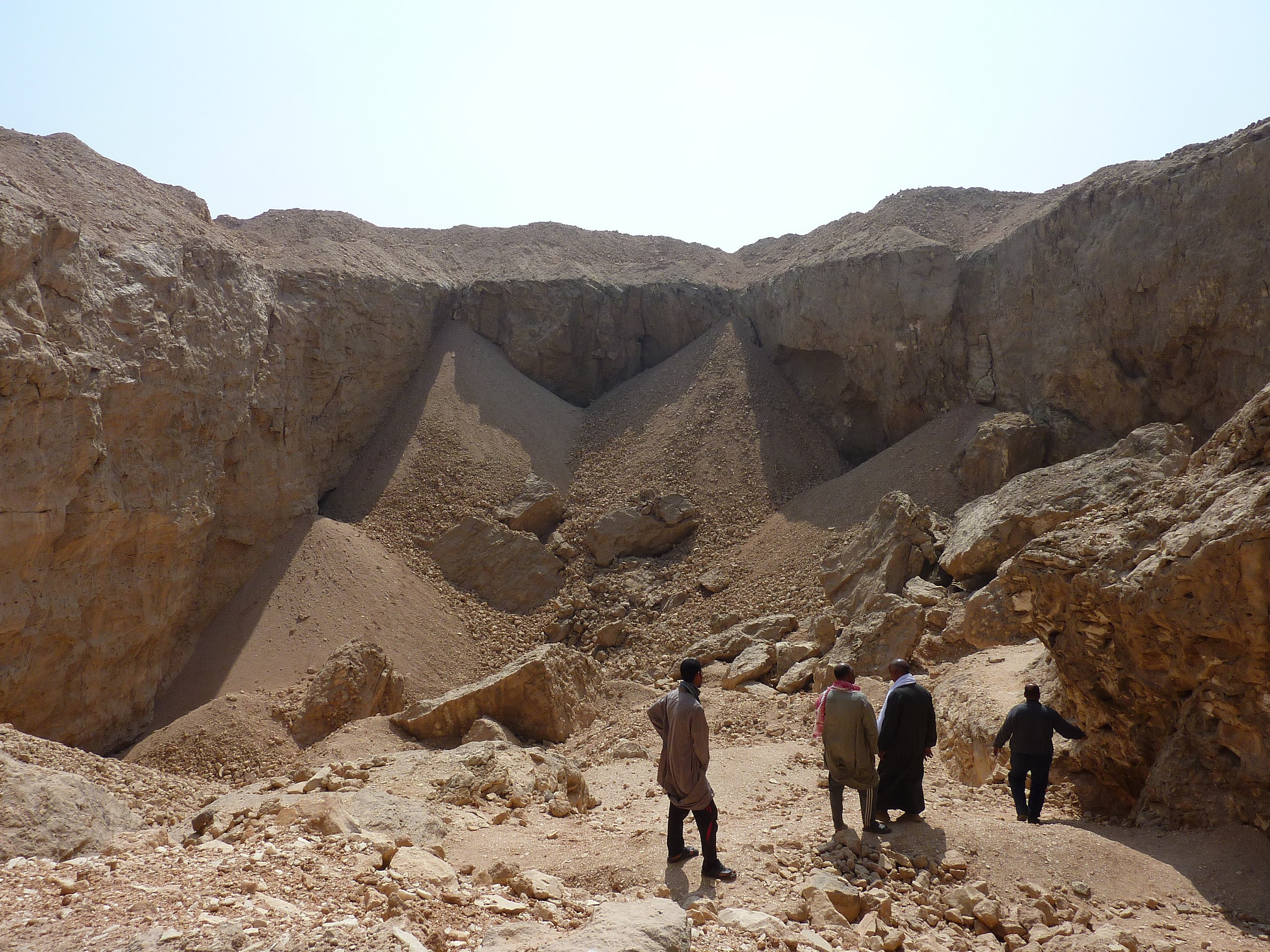
- Dead-End Tunnel: A purposeless tunnel extending from the Subterranean Chamber, reflecting exploratory excavation along a terminating fault line (Section 2).
- Erosion Patterns and Limescale in the Subterranean Chamber: Traces of water infiltration and limescale, indicating the chamber’s exposure to groundwater and its technical role (Section 2).
- External visible construction lines on the Great Pyramid correspond to the building platforms, highlighting the stepwise construction method (Section 3).
- Grand Gallery: Initially a counterweight chamber for the hoisting system, designed with a corbelled ceiling and niches to support mega-monolith transport (Section 5).
- Niches and Grooves in the Grand Gallery: 27 recesses and lateral grooves along the side walls, serving as anchoring points for crossbeams or partitions in the counterweight system (Section 5).
- North Face Corridor: A supply platform with a chevron roof, possibly serving as camouflage for the real entrance hidden below (Section 4 & 7).
- Pressure Shafts (2 x 2): Four narrow shafts (ventilation shafts) in the King’s Chamber and Queen’s Chamber, acting as pressure valves to regulate sand during construction (Section 9.2).
- Quartz Sand: Used as stabilizing material and functional ballast throughout the pyramid, not merely debris, found in nearly every cavity (Section 6 & 9).
- Rough Finish of the Subterranean Chamber: The irregular shape and rough finish, contrasting with the polished upper chambers, indicating its role as a technical reservoir for sand storage (Section 2 & 9.4).
- Unfinished Subterranean Chamber: A space for storing drained sand (approx. 450 m³), connected to the Well Shaft, designed as a terminal reservoir (Section 9.4).
- Unusual Perfection of the King’s Chamber: Driven by structural necessity for the hoisting and placement of monoliths in and upon the five relieving chambers (Section 10).
- Well Shaft and Grotto: A drainage system for transferring sand from the Grand Gallery and chambers to the Subterranean Chamber, with the Grotto reflecting the fault line used in planning (Section 2 & 9.4).
16 Closing Statement
The proposed Structure Perfect Integrated Lifting, Energy Efficiency Regulation System (Spileers) for the Great Pyramid is feasible within the limits of known Egyptian technologies. Although organic materials such as ropes and pulleys have since decayed, remaining structural elements, such as anchoring points in the Grand Gallery, the chevron roofs above the King’s Chamber, the North Face Corridor, and certainly the corbelled roof of the Grand Gallery, indicate technically advanced applications and large scale purposes. These indications support the idea that an external ramp, the North Face Corridor, the Big Void, and the Grand Gallery together formed an ingenious transport system. Just as in modern architecture, where the construction crane is sometimes integrated into the structure itself, here too the hoisting mechanism appears to have been part of the building. This enabled granite blocks of 50 to 78 ton to be brought not only to their place with remarkable precision but also perfectly positioned. The model aligns with recent measurements, muon-tomography, and archaeological data, and can be further strengthened by experimental reconstruction, similar to earlier studies such as those of Stonehenge (Richards, 2004). All this testifies to Hemiunu’s exceptional ingenuity and makes clear that the Great Pyramid is not only a fascinating monument but also a symphony of technical mastery, with Hemiunu as composer of stone and spatial insight. The only supernatural aspect in this entire story is the natural gift of Hemiunu as master architect; he was the very first supernatural genius known in our history.
17 References
- Arnold, Dieter. 1991. Building in Egypt: Pharaonic Stone Masonry. New York: Oxford University Press.
- Beltagy, A. 2022. “Mechanical Analysis of Ancient Hoisting Systems.” Journal of Archaeological Engineering, 12(3): 45–59.
- Bianchi, Robert S. n.d. Persoonlijke communicatie.
- Brier, Bob, en Jean-Pierre Houdin. 2008. The Secret of the Great Pyramid: How One Man’s Obsession Led to the Solution of Ancient Egypt’s Greatest Mystery. New York: HarperCollins.
- Bui, H. D. 2019. “Non-Destructive Testing and Evaluation of the Great Pyramid of Giza Using Muon Tomography.” Journal of Archaeological Science 105: 105–112. DOI: 10.1016/j.jas.2019.02.004.
- Dash, Glen. 2015. “The Great Pyramid’s Internal Ramp Hypothesis: A Reassessment.” Journal of Egyptian Archaeology 101: 45–60.
- Davison, Nathaniel. 1765. “Observations on the Pyramids of Gizeh”
- Dunand, M. 1950. Fouilles de Byblos. Paris: Librairie Orientaliste Paul Geuthner.
- Edgar, John, en Morton Edgar. 1910. Great Pyramid Passages and Chambers. Glasgow: Bone & Hulley.
- Edwards, Iorwerth E. S. 1993. The Pyramids of Egypt. Herziene editie. London: Penguin Books.
- Ghoneim, E., Sheisha, H., et al. (2024). The Egyptian pyramid chain was built along the now abandoned Ahramat Nile Branch. Communications Earth & Environment, 5: 231.
- Goyon, Georges. 1985. Les constructions et l’art architectural de l’Égypte ancienne. Paris: Éditions A. et J. Picard.
- Hassan, Selim. 1935. Excavations at Gîza: Season 1934-1935. Cairo: Government Press, Bulaq.
- Hawass, Zahi, en Mark Lehner. 1997. Giza and the Pyramids: The Definitive History. London: Thames & Hudson.
- Herodotus, Histories, 2.125
- Houdin, Jean-Pierre, en Christine Houdin. 2010. Khufu Reborn: The Inside Story of the Great Pyramid. Paris: Editions du Patrimoine.
- Isler, Martin. 2001. Sticks, Stones, and Shadows: Building the Egyptian Pyramids. Norman: University of Oklahoma Press.
- Lehner, Mark. 1997. The Complete Pyramids: Solving the Ancient Mysteries. London: Thames & Hudson.
- Lucas, Alfred, en J. R. Harris. 1962. Ancient Egyptian Materials and Industries. 4e editie. London: Edward Arnold.
- Maragioglio, V., & Rinaldi, C. (1965). L’Architettura delle Piramidi Menfite: Studio delle tecniche costruttive. Torino: Officina Edizioni.
- Moorey, P. R. S. 1994. Ancient Mesopotamian Materials and Industries. Oxford: Clarendon Press.
- Morishima, Kunihiro, Mitsuaki Kuno, Akira Nishio, et al. 2017. “Discovery of a Big Void in Khufu’s Pyramid by Observation of Cosmic-Ray Muons.” Nature552 (7685): 386–390. DOI: 10.1038/nature24647.
- Nature Portfolio (2024). Ancient Nile branch helped to build Egypt’s pyramids. Nature Middle East.
- Parry, Dick. 2005. Engineering the Pyramids. Stroud: Sutton Publishing.
- Petrie, William Matthew Flinders. 1883. The Pyramids and Temples of Gizeh. London: Field & Tuer.
- Romer, John. 2007. The Great Pyramid: Ancient Egypt Revisited. Cambridge: Cambridge University Press.
- Rossi, C. (2003). Architecture and Mathematics in Ancient Egypt. Cambridge University Press.
- Ryan, T., & Hansen, K. 2023. “Rope Technology in Ancient Egypt: Braiding Techniques and Load Capacity.” Journal of Archaeological Materials, 15(2): 112–130.
- Scan-Pyramids Project. 2017–2024. Official Reports on Muon-Tomography of the Great Pyramid of Giza. Cairo: Heritage Innovation Preservation (HIP) Institute and University of Cairo.
- Sheisha, H., et al. (2022). Nile waterscapes facilitated the construction of the Giza pyramids during the 3rd millennium BCE. Proceedings of the National Academy of Sciences, 119(35): e2202530119.
- Smith, Craig B. 2004. How the Great Pyramid Was Built. Washington, DC: Smithsonian Books.
- Tallet, Pierre. 2017. Les papyrus de la mer Rouge: Le journal de Merer et les secrets des pyramides. Paris: Les Belles Lettres.
- Verner, Miroslav. 2001. The Pyramids: Their Archaeology and History. New York: Grove Press.
- Vyse, Richard William. 1837. Operations Carried on at the Pyramids of Gizeh in 1837, Volume 1
See the paper here: https://doi.org/10.5281/zenodo.17447052
“Absolutely remarkable! Spileers succeeds in explaining what many consider unsolvable, combining technical precision, archaeological observation, and logical consistency. The way he links the Grand Gallery, counterweights, and the Subterranean Chamber mechanically and historically is masterful. His calculations and interpretations of physical traces make this paper not only convincing but groundbreaking, shedding new light on the construction of the Great Pyramid. A must-read for anyone seeking to truly understand the building logic!”
The best and most logical theory I’ve ever seen, explaining everything with the fewest assumptions, following Occam’s razor.
It’s pretty well established that the building stones were raised by floating rafts on water. There is a series of canals that carried water to the base. The interior shaft and valve acted as a pump. Successive coffer dams and locks raised the stones level by level.
Deze uitleg veronderstelt kanalen, sluizen, cofferdammen, kleppen en pompen waarvoor geen enkel archeologisch spoor bestaat in of rond de Grote Piramide. Er zijn geen uitsparingen, geen slijtage, geen resten. Bovendien is waterdruk fysisch onmogelijk te beheersen voor blokken van 80 ton. Tegelijk verklaart dit model de bestaande interne architectuur — Grote Galerij, Big Step, nissen en groeven — op geen enkele manier.
Wow! Extremely thorough. Well done!
Of all existing theories,this one possesses the greatest explanatory power with the fewest additionnal assumptions,which not only makes it by far the most robust against future discoveries, but also ensures that any such discoveries can only serve to confirm it.
Spileers has solved the enigma of how the pyramid was built in a functional and coherent way.All other models are fragmentary and incomplete.
You must check out chapter 5.4 in order to understand Mr. Spileers’ theory andassumptions. Its the clue to eve rything. It gives us the explanation on how this pyramid could hold on its feet.